Intelligent universel afbryder W2-serien
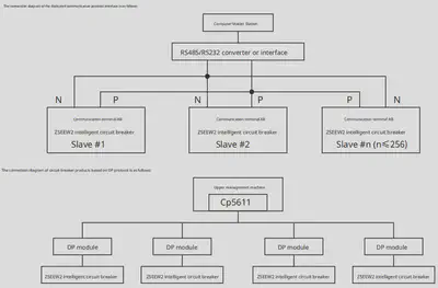
Intelligent universal circuit breaker: ZSEE W2 series (hereinafter referred to as the circuit breaker) is suitable for distribution networks with AC 50Hz, rated voltage up to 690V, and rated current of 6300A and below. It is used to distribute electric power and protect lines, power equipment, and motors from overload, undervoltage, short circuit, single-phase grounding, and other faults. The circuit breaker can be equipped with various intelligent controllers, providing comprehensive protection functions. The communication-type intelligent controller is equipped with a communication interface, facilitating connection with field buses and enabling remote measurement, remote adjustment, remote control, and remote signaling to meet the requirements of automated control. By configuring leakage transformers and corresponding intelligent controllers, it can also provide leakage protection.
Standards Compliance
GB/T 14048.2 “Low-voltage Switchgear and Controlgear Low-voltage Circuit Breakers”
IEC60947-2 “Low-voltage Switchgear and Controlgear Circuit Breakers”
Application Environment and Usage
-
Ambient air temperature is -5℃~+40℃, with the average value over 24 hours not exceeding +35℃;
Note: If the upper limit exceeds +40℃ or the lower limit is below -5℃, it needs to be specified.
-
When the maximum temperature is +40℃, the relative humidity of the air should not exceed 50%. Higher relative humidity is allowed at lower temperatures, for example, up to 90% at 20℃. Special measures should be taken to prevent condensation due to temperature changes;
-
Installation altitude should not exceed 2000m;
-
Pollution degree: Grade 3;
-
Protection level: IP40;
-
Vertical installation inclination should not exceed 5°;
-
Usage category B;
-
Main circuit installation category IV; the installation category of auxiliary circuits, except for the undervoltage release coil and the primary coil of the power transformer which are the same as the circuit breaker, is Category III;
-
Transport and storage conditions: -40℃~+70℃.
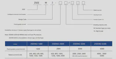
Model Explanation
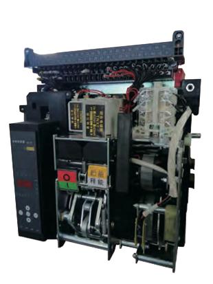
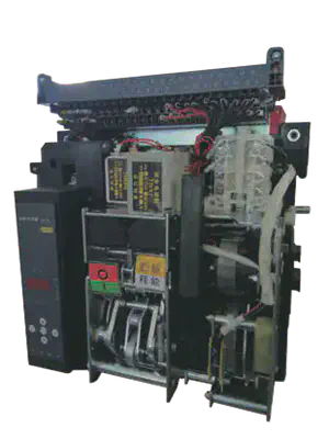
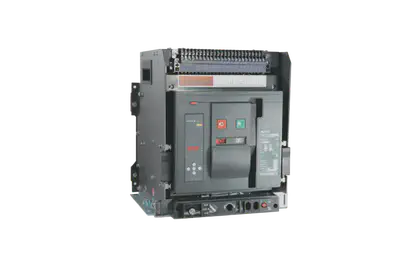
Product Structure
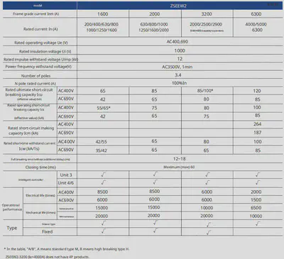
Main Technical Data and Performance Indicators
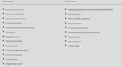
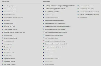
Intelligent Controller Classification and Function Introduction
Intelligent Controller Protection Characteristics
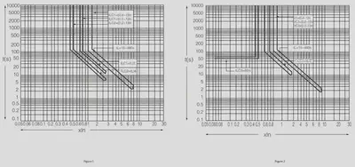
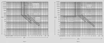
- Overload long-delay protection action characteristics.
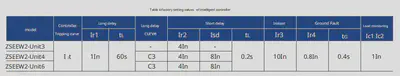
- The setting range I/In and accuracy of the intelligent controller can be found in Table 1.
- The inverse time delay characteristics of the delayed overcurrent protection can be found in Table 2. Its inverse time curve conforms to the P2T, = (1.5Ir1)?t characteristic curve. In this equation, ! is the actual operating current; T, is the actual operating time of the long delay; t is the set time of the long delay at 1.5Ir1.
- Short-delay overcurrent protection action characteristics.
- The protection characteristics of the controller are inverse time at low multiples of current. Its inverse time curve conforms to PTS = (8Ir1)ts (where Ts is the actual operating time of the short delay; ts is the set time of the short delay). When the overload current I>8Ir1, it should automatically switch to a definite time characteristic, as shown in Table 3.
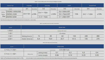
- The overcurrent protection characteristics of the intelligent controller can be seen in Figure 1.
- The ground fault protection characteristic curve can be seen in Figure 2.
- Ground fault protection is divided into two types: one detects the neutral current. When the three-phase currents are balanced, the neutral current is zero. When the three-phase currents are unbalanced and the neutral current exceeds the set value, the intelligent controller will give an alarm and, after the preset delay time, issue a command as required to either open or not open the circuit breaker. The other type detects the grounding line current. When the current exceeds the set value, the intelligent controller will give an alarm and, after the preset delay time, issue a command as required to either open or not open the circuit breaker. The ground fault protection characteristic is a definite time characteristic.
Intelligent Controller Protection Characteristics
Product Accessories


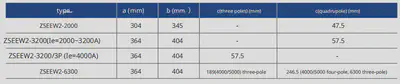
Dimensions and Installation Size
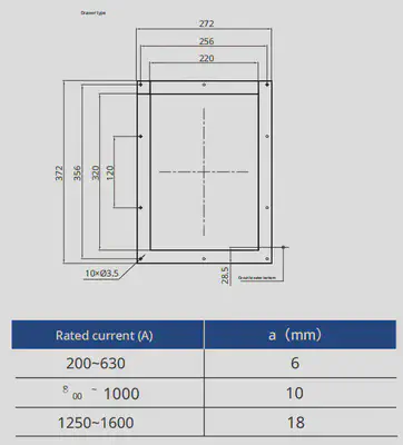
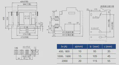
ZSEEW2-1600 Drawer-type circuit breaker dimensions and installation size (unit: mm)
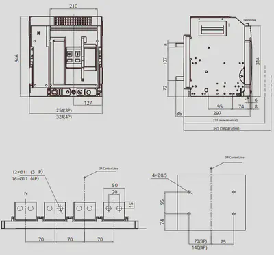
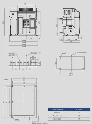
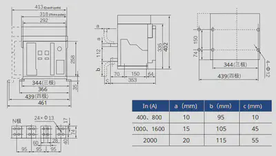
ZSEEW2-1600 Fixed-type circuit breaker dimensions and installation size (unit: mm)
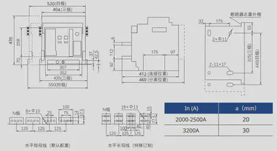
ZSEEW2-2000 Drawer-type circuit breaker L-type vertical wiring dimensions and installation size (unit: mm)
ZSEEW2-2000 Fixed-type circuit breaker L-type vertical wiring dimensions and installation size (unit: mm)
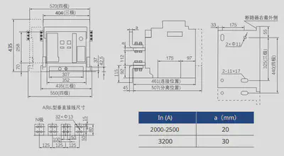
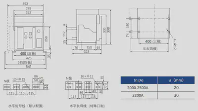
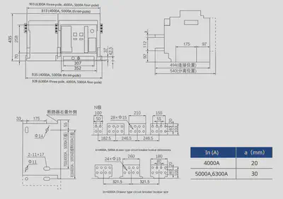
ZSEEW2-3200 (Ie=2000~3200A) skuffemonteret afbryder, L-formet lodret ledningslayout og installationsmål (enhed: mm)
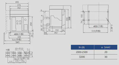
ZSEEW2-3200 (Ie=2000~3200A) fast afbryder, L-formet lodret ledningslayout og installationsmål (enhed: mm)
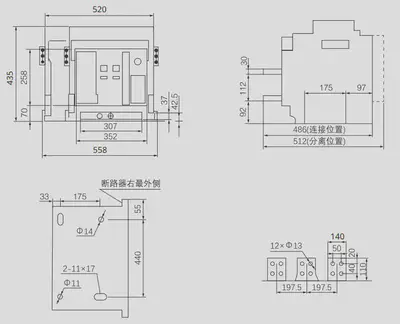
ZSEEW2-3200 (Ie=2000~3200A) skuffemonteret afbryder, vandret ledningslayout og installationsmål (enhed: mm)
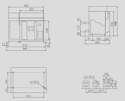
ZSEEW2-3200 (Ie=2000~3200A) fast afbryder, vandret ledningslayout og installationsmål (enhed: mm)
ZSEEW2-3200/3P (Ie=4000A) skuffemonteret afbryder, vandret ledningslayout og installationsmål (enhed: mm)
ZSEEW2-3200/3P (Ie=4000A) fast afbryder, vandret ledningslayout og installationsmål (enhed: mm)
ZSEEW2-6300 skuffemonteret afbryder, vandret ledningslayout og installationsmål (enhed: mm)
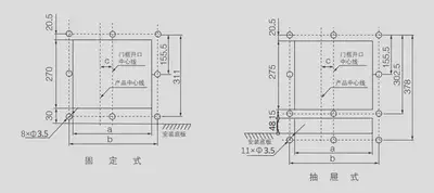
Paneludskæring og installationsmål som vist nedenfor (enhed: mm)
Elektrisk ledningsdiagram
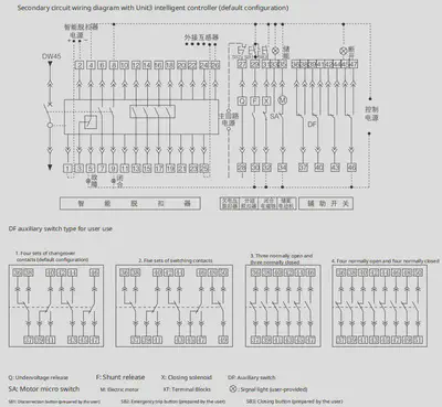
Bemærk: Beskrivelse af sekundære kredsløbsudgange:
- Den røde stiplede del tilsluttes af brugeren selv. Sørg for at beskytte kontrolkredsløbet med en sikring.
- 1# og 2#: Indgang til hjælpeforsyning; ved DC er 1# positiv og 2# negativ.
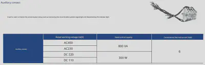
- 3#, 4#, 5#: Fejludløsende kontaktudgang (4# er fællesudgang). Kontaktkapacitet: AC380V, 16A.
- 6#, 7# og 8#, 9#: To sæt hjælpepunkter for afbryderstatus. Kontaktkapacitet: AC380V, 16A. Hvis brugeren ønsker det, kan terminalerne 6# og 7# levere en normalt lukket kontakt.
- 20#: Beskyttelsesjordledning.
- 21#, 22#, 23#, 24#: Indgangsterminaler for spændingssignaler (N, A, B, C i korrekt rækkefølge). Bemærk: Standardprodukter har ikke spændingsmåler, men denne funktion kan tilføjes ved specialbestilling, og omkostningerne vil blive faktureret særskilt.
- Hvis kontrolforsyningsspændingerne for Q, F, X, M er forskellige, kan de tilsluttes forskellige strømforsyninger. Underspændingsudløseren skal være direkte forbundet til det autonome kredsløb for at forbedre strømforsyningens pålidelighed og sikkerhed.
- Standardspecifikationen for hjælpekontakter er 4 skiftegrupper. Hvis andre typer er nødvendige, skal det angives ved bestilling.
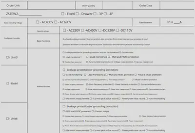
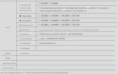
Bestillingsspecifikation
- Da vores produkters teknologi løbende opgraderes og optimeres, er al produktinformation i dette materiale underlagt de faktiske produkter. Ændringer kan forekomme uden forudgående varsel. Eventuelle tvister, der opstår som følge af oplysninger i dette materiale, som ikke er bekræftet af vores salgsafdeling, vil ikke medføre noget ansvar for vores virksomhed eller dens ansatte.