Control and Protection Switchgear
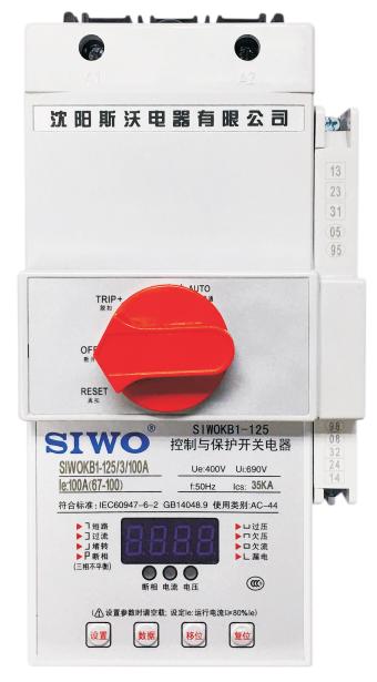
Control and Protection Switchgear: ZSEE KB1 series is designed based on the requirements of the smart grid, integrating the main functions of separate components such as circuit breakers, contactors, overload relays, isolating switches, and current-voltage meters into a modular single structure. It is capable of integrating various signals to achieve control and protection characteristics internally, using third-generation product protection technology. It features a compact size, high short-circuit breaking performance, long mechanical and electrical life, high operational reliability, safety and convenience in use, and energy and material savings.
The control and protection switchgear developed using advanced MCU and DSP control technology has high protection accuracy, stable and reliable operation, strong anti-interference ability, and realizes the digitalization, intelligence, communication networking, and field bus connection monitoring functions of the control and protection switch. It adopts energy-saving technology with low control power consumption and stable, reliable performance.
Standards Compliance
GB14048.1 “Low-voltage switchgear and controlgear Part 1 - General rules”
GB14048.9 “Low-voltage switchgear and controlgear Part 6-2 - Control and protection switchgear (device) CPS”
IEC60947-6-2 “Low-voltage switchgear and controlgear Part 6 - Multifunctional equipment Section 2 - Control and protection switchgear”
Operating Environment
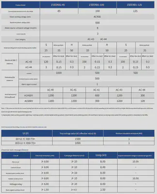
Operating Temperature: The upper limit of the ambient air temperature is +40°C, with an average value not exceeding +35°C within 24 hours, and a lower limit of -5°C.
Altitude: The installation site altitude should not exceed 2000m.
Relative Humidity: The relative humidity of the air at the installation site should not exceed 50% when the maximum temperature is +40°C; higher relative humidity is permissible at lower temperatures. The monthly average minimum temperature of the most humid month should not exceed +25°C, and the monthly average maximum relative humidity should not exceed 90%. Condensation on the product due to humidity changes must be prevented.
Installation Category: Category IV for 400V systems.
Protection Level: IP12 (with finger protection function).
Pollution Degree: Level 3. It can also be used in other pollution degrees depending on the microenvironment.
Application Fields and Uses
The ZSEEKB1 is suitable for pump, fan, air conditioning, and fire lighting control systems in modern buildings; motor control and protection in fields such as metallurgy, coal mining, steel, petrochemical, ports, ships, railways, and textiles; and single motor control and protection or remote lighting system control in factories or workshops.
The ZSEEKB1 control and protection switchgear is mainly used in power systems with AC 50Hz (60Hz), rated insulation voltage up to 690V, and rated current from 1A to 125A. It can connect, carry, and break currents under normal conditions, including specified overload conditions, and can connect, carry, and break currents under specified abnormal conditions (e.g., short-circuit currents). The ZSEEKB1 can perform comprehensive parameter measurements, serving both as a protection mechanism and a comprehensive sensor.
Functions and Features
Efficient Energy Saving, Low Temperature Rise
The ZSEEKB1 control and protection switch adopts advanced energy-saving technology. Its electromagnetic system utilizes a start current circuit and a holding current circuit, with AC starting and MCU-controlled DC holding, reducing the power loss of the electromagnetic system and short-circuit ring, saving energy and reducing temperature rise and noise.
Reliable Performance, Long Lifespan
The ZSEEKB1 control and protection switch has a buffer device in its electromagnetic system, reducing energy impact and enhancing the performance of the switch, thereby extending its lifespan. It uses high-quality industrial-grade MCUs and brand-name electronic components with well-designed circuits, reducing electromagnetic interference and improving product reliability.
Specific Functions and Features:
- Remote automatic control and local manual control.
- Panel indication and electromechanical signal alarm functions.
- Coordinated time-current protection characteristics (long-time, short-time short-circuit, instantaneous three-stage protection characteristics).
- Protection functions such as phase loss, overcurrent, stall, short-circuit, undercurrent, overvoltage, undervoltage, leakage, phase imbalance, and start delay (to avoid large start current and differentiate from overcurrent action time).
- LED display for various operating fault statuses, with voltage and current meter functions.
- Parameters can be set and queried through the operation panel. EEPROM memory technology is used for non-volatile data storage.
- Fault memory function for fault inquiry and analysis.
- RS485 communication interface and open field bus (Modbus protocol, etc.), facilitating system integration and intelligent management.
Users can choose functional modules or accessories as needed to achieve control and protection of various motor and distribution loads.
Flexible Installation
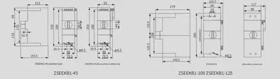
Horizontal, vertical, and level installations do not affect performance. 45-frame products can be installed on rails or fixed.
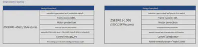
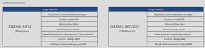
Model Description
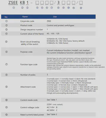
Table 1: Control Mode Codes
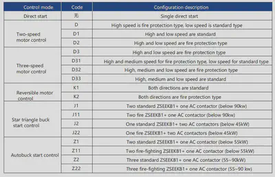
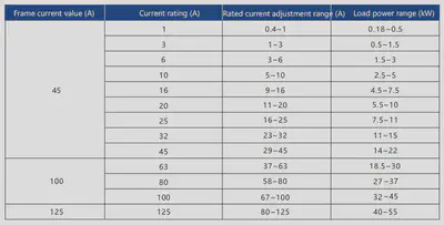
Table 2: Frame and Rated Current Correspondence Table
Characteristic Parameters
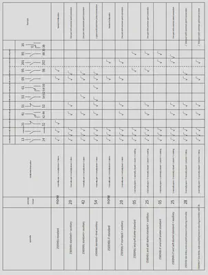
Optional Accessory Configuration Table
Main Structure and Working Principle
The ZSEEKB1 control and protection switchgear mainly consists of a base, electromagnetic mechanism, operating mechanism, main circuit contact group, MCU intelligent control detection system, and electronic trip system.
Electromagnetic Mechanism
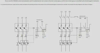
The electromagnetic mechanism of the ZSEEKB1 control and protection switch consists of a coil, core, control contact, base, etc. (similar to the electromagnetic control system of a contactor with undervoltage protection function). It can receive on-off operation commands to control the main contact in the main electrical contact group to connect or disconnect the circuit.
The electromagnetic mechanism of the ZSEEKB1 control and protection switch adopts advanced energy-saving technology, reducing the power loss of the electromagnetic system and short-circuit ring, saving energy. It also includes a buffer device to reduce energy impact, enhancing the performance and lifespan of the switch.
Operating Mechanism
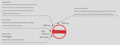
The operating mechanism of the ZSEEKB1 control and protection switch receives short-circuit signals from each pole contactor and output signals from the MCU intelligent control detection system. It cuts off the coil circuit through control contacts, allowing the electromagnetic mechanism to break the main circuit. After fault elimination, it resets through the operating knob.
The working status of the operating mechanism and the position of the knob indicators are shown on the main panel.
Operation Panel
MCU Intelligent Control Detection System
The specific functions of the MCU intelligent detection system of the ZSEEKB1 control and protection switch are described in “Specific Functions and Features.”
Intelligent Tripper
It features functions such as overload, overcurrent protection, phase imbalance, overvoltage, undervoltage, phase loss, and undercurrent. The settings include overload inverse time limit and overcurrent fixed time limit, with adjustable current values.
Working Principle
Operating Instructions
Operating Instructions
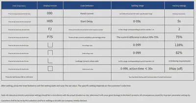
- Set Key: Press this key to enter the protection parameter setting mode when the motor is not running.
- Data Key: Modify the flashing digit position. Each press increments the number by 1, cycling from 0 to 9.
- Shift Key: Select the set digit position (flashing) in the setting mode.
- Reset Key: After completing the parameter setting, press this key to save the settings and enter the normal monitoring mode.
Operating Procedures
After ZSEEKB1 is powered on without load, the LED displays the voltage value and can also function as a voltmeter, with the last three digits showing the voltage value.
During operation, ZSEEKB1 can function as an ammeter, cyclically displaying the operating conditions of the three-phase current.
Press the shift key to display the operating conditions of phase A, phase B, phase C, and L (leakage) currents in turn.
Press the reset key to resume cyclic display of the three-phase current operating conditions.
Fault Inquiry
With ZSEEKB1 running without load, press the data key. By comparing with the panel fault type symbols, the previous three fault types can be queried. When the voltage value is displayed, it indicates that ZSEEKB1 has exited the fault inquiry and entered normal monitoring. Alternatively, restart ZSEEKB1 to exit fault inquiry.
Protection Parameter Settings
During motor startup and operation, pressing the setting button has no effect;
Idle running ZSEEKB1;
Press the setting button to select the setting type, press the shift key in sequence to select data shift, and press the data key to modify the data;
Once a parameter is set, press the setting button again to enter the next setting state until the process is complete;
Unnecessary options should be skipped. After all parameters are set, press the reset button to exit the setting state and display the voltage value.
ZSEEKB1 Operation Sequence
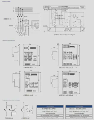
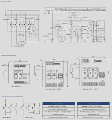
Dimensions and Installation Size
Wiring Diagram
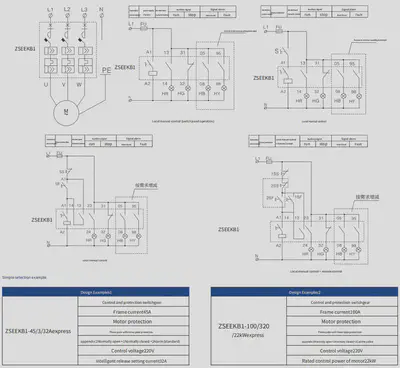
ZSEEKB1-G Isolated Control and Protection Switchgear
Function Overview
The ZSEEKB1-G control and protection switchgear is suitable for isolating power sources in motor circuits and distribution circuits, meeting both main circuit isolation requirements and control circuit isolation needs. Its status is clearly indicated by the ON/OFF position indicator (operating knob). The main module parameters are the same as the standard ZSEEKB1 model.
Isolation Lock
The ZSEEKB1 isolated control and protection switchgear is equipped with a locking device in the isolation position of the handle, allowing a padlock to be attached. The padlock must be provided by the user.

Operation Panel

Product Forms
- Fire Isolation Control and Protection Switchgear ZSEEKB1-FG
- Communication Isolation Control and Protection Switchgear ZSEEKB1-NG
- Leakage Isolation Control and Protection Switchgear ZSEEKB1-GL
- Distribution Isolation Control and Protection Switchgear ZSEEKB1-PG
- Isolated Dual-Speed Motor Controller ZSEEKB1-GD
- Isolated Reversible Motor Controller ZSEEKB1-GK
- Isolated Star-Delta Reduced Voltage Starter ZSEEKB1-GJ
ZSEEKB1-F Fire Control and Protection Switchgear
Function Overview
The ZSEEKB1-F fire control and protection switchgear is mainly used in fire systems with AC 50Hz (60Hz), rated insulation voltage up to 690V, and rated current ranging from 1A to 125A. It can connect and carry current under normal conditions, including specified overload and overcurrent conditions, achieving the “alarm only, no trip” function, and can also connect, carry, and interrupt current under abnormal conditions (such as short-circuit currents), providing both alarm and trip functions.
Application Notes
When the loss caused by sudden power failure is greater than the loss from overload operation, overload protection should not be installed. This applies to loads such as fire hydrant pumps, sprinkler pumps, and smoke exhaust fans. If overload protection is installed, during a fire, the overload protector may trip, causing fire-fighting equipment to malfunction and delaying fire extinguishing efforts, resulting in more severe losses. If overload protection is installed, it should trigger an alarm signal, alerting personnel to check and resolve the issue.
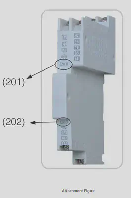
Accessory Notes
The ZSEEKB1-F fire control and protection switchgear, combined with other modules, can provide the “alarm only, no trip” function during faults. When overload or overcurrent faults occur (excluding short circuits), the switch panel indicator light displays the corresponding fault, and a pair of alarm contacts 201, 202 (normally open, closed during fault alarms) is output. See the right diagram for specific numbers:
Product Forms
- Fire Isolation Control and Protection Switchgear ZSEEKB1-FG
- Fire Leakage Control and Protection Switchgear ZSEEKB1-FL
- Fire Distribution Control and Protection Switchgear ZSEEKB1-PF
- Fire Communication Control and Protection Switchgear ZSEEKB1-FN
ZSEEKB1-N Communication Control and Protection Switchgear
Function Overview
The ZSEEKB1 background software operates in the Windows 9X/NT/XP environment and provides a standard RS485 communication interface.
The interface module’s upper-level machine connection end is equipped with high-speed optical isolation, enhancing anti-interference capability. It supports multiple communication protocols, including Modbus, with a communication distance of up to 1200 meters. The system can simultaneously modify, set, transfer, record, and display various motor parameters for multiple CPS units.
Communication Network

ZSEEKB1 Control Software Functions
Main Functions:
- Remote setting of ZSEEKB1 switch parameters via software.
- Remote management of motors controlled by ZSEEKB1 via software.
- Real-time motor monitoring via software, displaying real-time voltage, current operation status, and fault types.
- Querying motor start/stop faults and other historical data via software.
Product Forms
- Communication Fire Control and Protection Switchgear ZSEEKB1-NF
- Communication Isolation Control and Protection Switchgear ZSEEKB1-NG
- Communication Leakage Control and Protection Switchgear ZSEEKB1-NL
- Distribution Communication Control and Protection Switchgear ZSEEKB1-PN
ZSEEKB1-L Leakage Control and Protection Switchgear
Function Description
The ZSEEKB1-L leakage control and protection switchgear measures motor operation and grounding fault conditions using a built-in zero-sequence transformer, determining whether to activate leakage protection based on the magnitude of the zero-sequence current.
Leakage Set Values
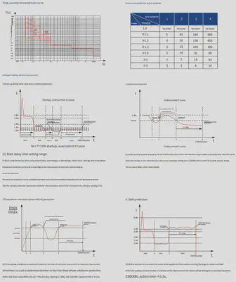
When the leakage is 100mA, the ZSEEKB1 response time is ≤0.2s. The leakage current value can be set according to user requirements based on preset value numbers. The leakage current values corresponding to the preset value numbers are shown in the table below (factory setting is 6):
Operation Description
During operation, the ZSEEKB1-L leakage control and protection switchgear alternately displays the three-phase current and leakage current, making it easy for users to monitor the leakage status of the load.
Product Forms
- Isolated Leakage Control and Protection Switchgear ZSEEKB1-GL
- Leakage Dual-Speed Control and Protection Switchgear ZSEEKB1-LD
- Fire Leakage Control and Protection Switchgear ZSEEKB1-FL
- Reversible Leakage Control and Protection Switchgear ZSEEKB1-LK
- Distribution Leakage Control and Protection Switchgear ZSEEKB1-PL
- Communication Leakage Control and Protection Switchgear ZSEEKB1-NL
- Leakage Star-Delta Reduced Voltage Starter ZSEEKB1-L J
ZSEEKB1-D Dual-Speed, Triple-Speed Motor Controllers
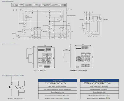
ZSEEKB1-D Dual-Speed Motor Controller
Function Overview
The ZSEEKB1 control and protection switch, combined with contactors and other accessories, forms the ZSEEKB1-D dual-speed motor controller, which is suitable for controlling and protecting dual-speed motors.
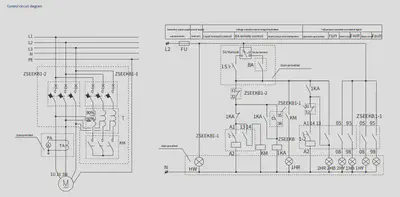
Control Principle
When the motor is used as a smoke exhaust fan, the ZSEEKB1-1 switch operates, and the motor runs at low speed; when the motor is used as a smoke exhaust fan, the ZSEEKB1-2 switch and the KM AC contactor operate, and the motor runs at high speed. Local or remote fire control is possible.
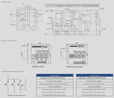
ZSEEKB1-D3 Triple-Speed Motor Controller
Function Overview
The ZSEEKB1 control and protection switch, combined with contactors and other accessories, forms the ZSEEKB1-D3 triple-speed motor controller, which is suitable for controlling and protecting triple-speed motors.
Control Principle
When the motor is used as an exhaust fan, the ZSEEKB1-1 switch operates, and the motor runs at low speed; when the ZSEEKB1-2 switch operates, the motor runs at medium speed; when the motor is used as a smoke exhaust fan, the ZSEEKB1-3 and the KM AC contactor operate, and the motor runs at high speed. Both local and fire control are possible.
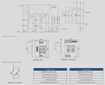
ZSEEKB1-K Reversible Motor Controller
Overview of Features
The ZSEEKB1-K reversible motor controller uses the ZSEEKB1 control and protective switchgear as the main switch. It is designed for controlling and protecting reversible motors.
Control Principle
When the ZSEEKB1-1 switch operates, the motor runs forward; when the ZSEEKB1-2 switch operates, the motor runs in reverse.
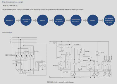
ZSEEKB1-J Star-Delta Reduced Voltage Starter Controller
Overview of Features
The star-delta reduced voltage starter controller is available in four configurations:
- Configuration 1: ZSEEKB1-J1, two standard ZSEEKB1 units + one AC contactor (90KW and below);
- Configuration 2: ZSEEKB1-J11, two fireproof ZSEEKB1 units + one AC contactor (90KW and below);
- Configuration 3: ZSEEKB1-J2, one standard ZSEEKB1 unit + two AC contactors (45KW and below);
- Configuration 4: ZSEEKB1-J22, one fireproof ZSEEKB1 unit + two AC contactors (45KW and below).
The product features and main circuit parameters are the same as those of the standard ZSEEKB1 or ZSEEKB1-F fireproof models. The attachments are chosen from the specialized type 28 series.
Control Principle
- Explanation of Configurations 1 and 2: When the ZSEEKB1-1 and the KM AC contactor operate, the motor starts in star mode. Once the built-in time delay of the ZSEEKB1 is completed, the KM AC contactor opens, and the ZSEEKB1-2 closes, switching the motor to delta mode.
- Explanation of Configurations 3 and 4: When the ZSEEKB1 and the KM1 AC contactor operate, the motor starts in star mode. Once the built-in time delay of the ZSEEKB1 is completed, the KM1 AC contactor opens, and the KM2 AC contactor closes, switching the motor to delta mode.
Note: The time delay of the ZSEEKB1 control and protective switchgear is adjustable.
ZSEEKB1-Z Autotransformer Reduced Voltage Starter Controller
Overview of Features
The ZSEEKB1-Z autotransformer reduced voltage starter controller is built using the ZSEEKB1 control and protective switchgear as the main switch, combined with AC contactors and other accessories. Through the built-in time-delay contacts of the ZSEEKB1, the ZSEEKB1-Z autotransformer reduced voltage starter controller is formed. It can also be assembled as a fireproof autotransformer reduced voltage starter controller ZSEEKB1-FZ, capable of controlling and protecting motors up to 90KW during autotransformer reduced voltage starting.
- Due to continuous upgrades and optimization of the company’s products, all information contained in this document is subject to the actual product. If there are any changes, no further notice will be given. The company and its employees do not bear any joint liability for disputes arising from any unconfirmed information contained in this document.