Intelligent Universal Circuit Breaker W2 Series
Intelligent Universal Circuit Breaker: ZSEE W2 Series (hereinafter referred to as the circuit breaker) is suitable for AC 50Hz, rated voltage up to 690V, and rated current up to 6300A distribution networks. It is used for distributing electrical energy and protecting circuits, power equipment, and motors from overload, undervoltage, short circuit, single-phase grounding, and other faults. The circuit breaker can be equipped with various intelligent controllers that offer comprehensive protection functions. The communication-type intelligent controller has a communication interface for easy connection to the fieldbus, enabling remote measurement, remote adjustment, remote control, and remote signaling functions to meet the requirements of control automation. With the addition of a leakage transformer and corresponding intelligent controller, it can also provide leakage protection.
Compliance Standards
GB/T 14048.2 “Low-voltage switchgear and controlgear—Part 2: Circuit breakers for low-voltage switchgear and controlgear”
IEC 60947-2 “Low-voltage switchgear and controlgear—Part 2: Circuit breakers”
Operating Environment and Application
-
Ambient air temperature: -5℃ to +40℃; with a 24-hour average not exceeding +35℃.
Note: If the upper limit exceeds +40℃ or the lower limit is below -5℃, it must be specified.
-
When the maximum temperature is +40℃, the relative humidity of the air does not exceed 50%. Higher relative humidity is allowed at lower temperatures, for example, 90% at 20℃. Special measures should be taken to prevent condensation due to temperature changes.
-
Installation site altitude: not more than 2000m.
-
Pollution level: Grade 3.
-
Protection level: IP40.
-
Vertical inclination of installation: not more than 5°.
-
Utilization category: B.
-
Main circuit installation category: IV; for auxiliary circuits, except for the undervoltage trip coil, the primary coil of the power transformer has the same installation category as the circuit breaker, i.e., category III.
-
Transportation and storage conditions: -40℃ to +70℃.
Model Description
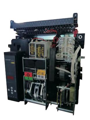
Product Structure
Main Technical Data and Performance Indicators
Intelligent Controller Classification and Function Description
Intelligent Controller Protection Characteristics
-
Long-time delay overload protection characteristics.
-
The setting range I/In and accuracy of the intelligent controller are shown in Table 1.
-
The inverse time delay overcurrent protection characteristics are shown in Table 2. The inverse time delay curve conforms to the P2T characteristic curve, where T is the actual operating current, and t is the long-time delay setting time for 1.5Ir1.
-
Short-time delay overcurrent protection characteristics.
-
The controller’s protection characteristics are inverse time delay at low multiples of current. The inverse time delay curve conforms to PTS characteristics (where Ts is the actual operating time and ts is the set time for short-time delay). When the overload current I > 8Ir1, it should automatically switch to fixed-time limit characteristics, as shown in Table 3.
-
The overcurrent protection characteristics of the intelligent controller are shown in Figure 1.
-
Ground fault protection characteristic curve is shown in Figure 2.
-
There are two types of ground fault protection: one is to detect the neutral point current. When the three-phase current is balanced, the neutral point current is zero. If the three-phase current is unbalanced, and the neutral point current exceeds the set value, the intelligent controller alarms. After the set delay time, it sends a command as required to either trip or not trip the circuit breaker. The other is to detect ground line current. When the current exceeds the set value, the intelligent controller alarms and, after the set delay time, sends a command as required to either trip or not trip the circuit breaker. Ground fault protection is fixed-time limit.
Intelligent Controller Protection Characteristics
Product Accessories
Dimensions and Installation Sizes
ZSEE W2-1600 Draw-out Type Circuit Breaker Dimensions and Installation Sizes (unit: mm)
ZSEE W2-1600 Fixed Type Circuit Breaker Dimensions and Installation Sizes (unit: mm)
ZSEE W2-2000 Draw-out Type Circuit Breaker L-type Vertical Wiring Dimensions and Installation Sizes (unit: mm)
ZSEE W2-2000 Fixed Type Circuit Breaker L-type Vertical Wiring Dimensions and Installation Sizes (unit: mm)
ZSEE W2-3200 (Ie=2000~3200A) Draw-out Type Circuit Breaker L-type Vertical Wiring Dimensions and Installation Sizes (unit: mm)
ZSEE W2-3200 (Ie=2000~3200A) Fixed Type Circuit Breaker L-type Vertical Wiring Dimensions and Installation Sizes (unit: mm)
ZSEE W2-3200 (Ie=2000~3200A) Draw-out Type Circuit Breaker Horizontal Wiring Dimensions and Installation Sizes (unit: mm)
ZSEE W2-3200 (Ie=2000~3200A) Fixed Type Circuit Breaker Horizontal Wiring Dimensions and Installation Sizes (unit: mm)
ZSEE W2-3200/3P (Ie=4000A) Draw-out Type Circuit Breaker Horizontal Wiring Dimensions and Installation Sizes (unit: mm)
ZSEE W2-3200/3P (Ie=4000A) Fixed Type Circuit Breaker Horizontal Wiring Dimensions and Installation Sizes (unit: mm)
ZSEE W2-6300 Draw-out Type Circuit Breaker Horizontal Wiring Dimensions and Installation Sizes (unit: mm)
Panel Cut-out and Installation Dimensions are as follows (unit: mm)
Electrical Schematic Diagram
Note: Secondary Circuit Output Description:
- The red dashed part is connected by the user, and fuse protection should be added to the control circuit.
- 1#, 2#: Auxiliary power input terminals, 1# is positive and 2# is negative in the case of DC.
- 3#, 4#, 5#: Fault trip contact output (4# is the common terminal), contact capacity: AC380V, 16A.
- 6#, 7# and 8#, 9#: Two groups of auxiliary terminals for circuit breaker status, contact capacity: AC380V, 16A. If requested by the user, terminal 6# and 7# can output normally closed contacts.
- 20#: Protective grounding wire.
- 21#, 22#, 23#, 24#: Voltage signal input terminals (N, A, B, C in sequence, do not connect incorrectly). Note: Regular products do not have a voltmeter function. When a special order requires a voltmeter function, additional charges apply.
- If the control power voltages of Q, F, X, and M are different, they can be connected to different power sources respectively. The undervoltage trip must be directly connected to the independent circuit power supply to enhance the reliability and safety of the power supply.
- The auxiliary switch is configured with 4 groups of conversions by default. If the user needs other types, please specify when ordering.
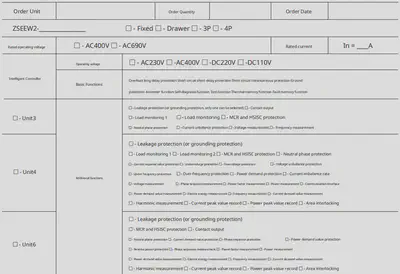
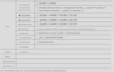
Ordering Specifications
- Due to continuous technological upgrades and optimizations of the company’s products, all information in this document is subject to the actual product. Changes may be made without prior notice. The company and its employees shall not bear any liability for disputes arising from information in this document that has not been confirmed by our business department.